
- #SERVO MOTOR ARDUINO SCHEMATIC HOW TO#
- #SERVO MOTOR ARDUINO SCHEMATIC FULL#
- #SERVO MOTOR ARDUINO SCHEMATIC OFFLINE#
- #SERVO MOTOR ARDUINO SCHEMATIC DOWNLOAD#
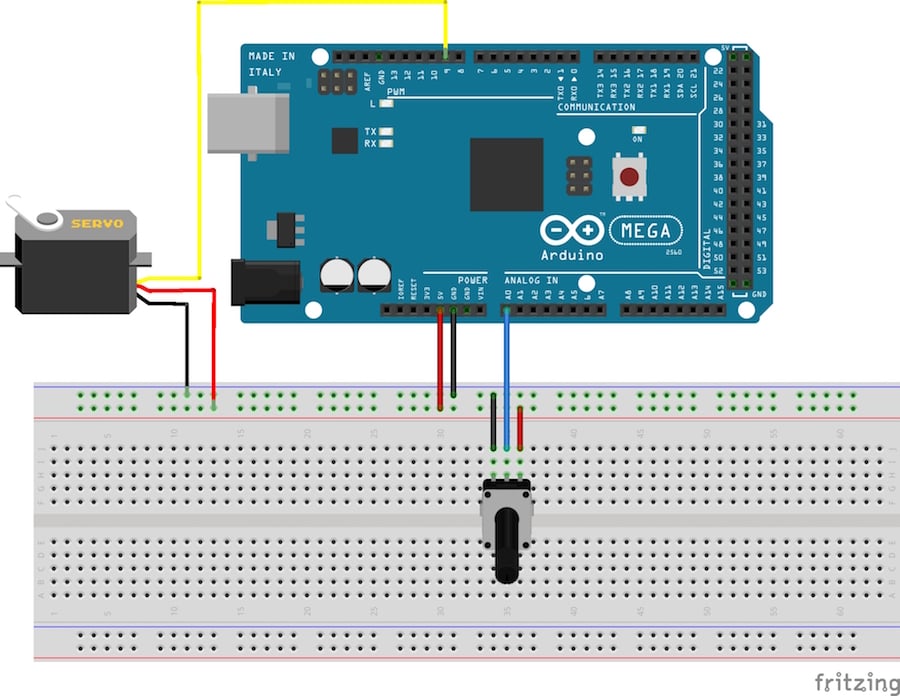
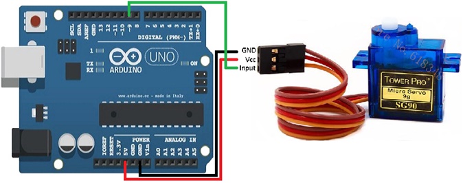
Int pos = 0 // variable to store the servo position a maximum of eight servo objects can be created Mate with Arduino and Arduino compatible boards Provides connectors to support 2 servos Integrated pull down resistor to keep motor disable during start. Servo myservo // create servo object to control a servo So, you can follow the next schematic diagram to wire your servo motor.
#SERVO MOTOR ARDUINO SCHEMATIC OFFLINE#
This is done with the help of the Servo library, which is pre-installed library in the Arduino IDE (both offline and online versions). In our examples well connect the signal wire to GPIO 13.
#SERVO MOTOR ARDUINO SCHEMATIC HOW TO#
In this project, we need Servo library developed by the Arduino team to facilitate the use of servo motors in Arduino projects. In this tutorial, we will learn how to control a standard servo motor, to go back and forth across 180 degrees, using a for loop ().

They are already built in the Proteus ISIS and connected to +VCC and ground pins as shown in below. The primary components for this circuit are: Arduino Uno - R3. In Proteus you need to connect the +5v and ground pins to servo motor. Learn how to wire the Continuous Rotation Micro Servo to Arduino Uno in a few simple steps. servo motor connection, How to Control Servo Motors with Arduino, - Potentiometer Servo Motor Tutorial, How to Control Servos With the Circuit Basics. Servo Motor has three pins, one of them goes to Vcc, other one to GND while the center pin is the controlling pin and goes to any digital PIN 9 of Arduino board. Servo Motor has quick response and high speed. This motor can be utilized to manage the robotic vehicle by controlling robot speed, create plenty torque to move and also start and stop the robot. If it required turning only a small amount, the motor will run at a slower speed.
#SERVO MOTOR ARDUINO SCHEMATIC FULL#
So, if the shaft required turning a large distance, the motor will run at full speed. The power applied to the motor is proportional to the distance it required to travel. Caution: Do not try to rotate the servo motor by hand, as you may damage. Connect to the motor to the Arduino as shown in the table below: Servo red wire 5V pin Arduino. A simple servo is used to manage an angular motion of 0 to 180 degrees. The best thing about a servo motor is that it can be connected directly to an Arduino. Generally, it is somewhere in the 210-degree varies however, it range depending on the manufacturer. The servo motors power lines are connected to the 5 V and GND. Servo control Servo motors are controlled by sending a PWM (pulse-width modulation) signal to the signal line of the servo. Good for beginners who want to make stuff move without building a motor controller with.


The maximum speed of the output shaft is usually around 60 RPM. You can use any servo code, hardware or library to control these servos. The servo moves clockwise or counterclockwise (0 180) with the corresponding angular position of the potentiometer. At every instant, the servo arm follows the position of the Knob. 2018) The gearbox decreases the speed of the motor, which increases the torque at the output shaft. Servo motor position control arduino Here we are controlling the angular position of a servo motor using a potentiometer.
#SERVO MOTOR ARDUINO SCHEMATIC DOWNLOAD#
The output shaft of the servo have ability of traveling somewhere around 180 degrees. Download scientific diagram Figure B.4: Schematic of servo motor wired to the Arduino board. Schematic of an RC servo motor (Hwang et al. If the circuit sees that the angle is not correct, it will turn the motor until a desired angle. If the shaft is at the right angle, then the motor shuts down. In the sketch we will see servo motor take start from 0 to 190 and then wait for some time and then servo motor move to the position from 190 to 0, this is what happening in this project.The servo motor has some control circuits and a potentiometer attached to the output shaft. This is how to make schematic of servo with Arduino. In this tutorial we will learn how to interface Servo Motor with Arduino uno and wiring with it.


 0 kommentar(er)
